
Poor lubrication is a major cause of bearing failure. How do we make sure our bearings, gearboxes, and other components have the ideal lubricant film?
Figure 1 is a representation of what the inside of a rolling element bearing looks like. In most bearings, the inner race turns with the shaft, and the rolling elements roll in the opposite direction. The outer race is static in most operations.
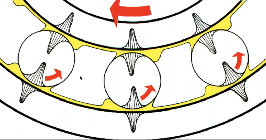
Figure 1: Inside a bearing
So there are different dynamics happening inside the bearing. The grease or oil should be filling the gaps between all of the metal surfaces. The parabolic shapes represent the load. The wider the distribution of the load, the longer the bearing life. The distribution depends on the lubricant properties along with the thickness of the lubricant film.
It is essential to keep your bearings properly lubricated. Make sure the surfaces are separated enough so that friction does not result in premature cracks and wear. The lubricant you use will depend on the shape of the bearing and the speed. This is called precision lubrication.
A perfect lubricant film will keep the load evenly distributed, as widely as possible. We use additives to ensure that happens. Above all, the lubricant film thickness is the most important consideration.
For example, a typical bearing in a high-speed motor will have a clearance of 4 to 6 microns at the top. That’s the area carrying the least amount of load. But down at the load zone, there would be a clearance of 1 to 3 microns.
Let’s look at a fault tree analysis covering most failures that happen in a bearing.
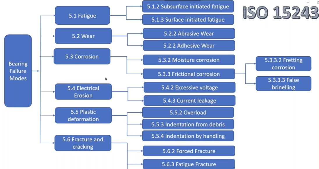
Figure 2: Fault Tree Analysis
Some of these failures are related to fatigue and wear, from too much load, and then there are some related to corrosion, electrical erosion, plastic deformation, and fracture and cracking.
Most of these are related to lubrication in some way. Improper lubrication directly leads to adhesive and abrasive wear. It is also connected to all types of corrosion. Lubricants by nature are electrical isolated, so electrical current will not pass through a sufficiently thick electrical film. Overloading and debris generation are also related to lubrication.
Forced fracture and fatigue fracture are somewhat out of our hands, and fatigue is related to the design of the material, but the whole area in the middle of the chart is related to lubrication. In every root cause analysis I have performed in my 15-year career, including the one shown in Figure 3, lubrication was involved.

Figure 3: Fault tree analysis
Excluding contamination issues, approximately 60% of bearing failures will be related to lubrication. And the problem is, one failure mode will cause others. For example, adhesive or abrasive wear will lead to particles in the metal, which will lead to surface fatigue wear, which will lead to another type of corrosive wear.
We use the Stribeck curve to find the ideal lubricant thickness. You can find more information about it online, but it is basically the relation between the film thickness, the coefficient of friction inside your bearing, and wear.
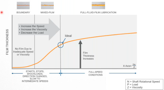
Figure 4: The Stribeck curve.
If you maintain an idea film thickness, the friction will reduce. Well, the friction is not really reducing, but it is happening in the lubricant rather than the metal, which is what we want. This will extend the bearing life.
Whenever you start the machine, as you increase the speed, you are generating more space for the film thickness to happen because the X-axis on this curve is always the viscosity multiplied by the shaft rotational speed—because those two factors work together to increase the film thickness—and then divided by the load.
So as you increase the speed, the viscosity does not change, but you generate the space for the viscosity to become a film. As the speed increases, the film thickness increases, until it gets to a point where it’s generating too much heat. Then the viscosity melts away, and you kill your curve.
We want to aim for the point where there is a full film separation between the bearing surfaces. But if the speed of the machine is below the ideal speed for this, the lubricant will need better additives.
Let’s talk about the coefficient of friction. This is the ratio of the force required to overcome friction to the load or pressure imposed between the surfaces of opposing bodies. This is the force we need to avoid friction.
A friction modifier is an additive, mainly a fatty acid we can add to reduce the starting friction. But in any case, friction reduces as velocity increases, until we reach an ideal point. And then friction will start increasing again because of the viscous drag. It’s like trying to run fast when you’re up to your knees in water. If you’re walking in the sea, you’re fine, but if you want to run, you will use more energy. That’s your coefficient of friction.
So at this point, we need to select a viscosity that is adequate for the speed of the application. If we add a friction modifier, it acts like soap and makes things slippery to reduce the startup friction. This additive is commonly used for start–stop applications such as engines or elevators, as well as slow-speed bearings that will never reach the ideal speed.
We also have an ideal point on the curve to avoid wear. Wear reduces with decreased friction and increased lubricant film thickness.
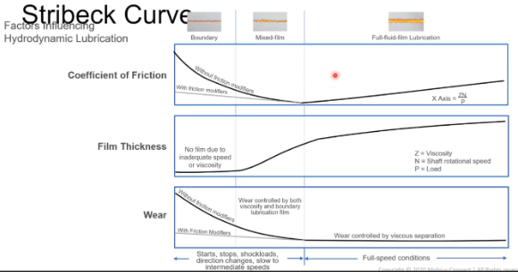
Figure 5: Three factors of the Stribeck curve
Ideally, we would like to be just at the right of the ideal point on the Stribeck curve. That is where the film is thick enough to result in the least wear and the least friction. Over my years in this industry, I have only found one technique to show you how to achieve this ideal point.
The Lambda λ ratio represents the thickness of the lubricant film in relation to the roughness of the two surfaces. The greater the Lambda, the greater the clearance. This is described in ISO 281. Figure 6 lists the Lambda for gear teeth and bearings.
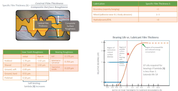
Figure 6: The Lambda
The Lambda is the central film thickness divided by the composite surface roughness. If the λ is less than 1, you have boundary lubrication, meaning asperities are banging against each other. This will result in lots of adhesive wear.
If the λ is from 1 to 3, this is mixed lubrication, which will result in adhesive wear and two-body abrasion. To achieve hydrodynamic lubrication, the λ must be greater than 3.
Luckily, SPM has created applications that allow us to see the film thickness and the separation of surfaces happening—or not happening—inside the bearing.
