
We used HD technology in several case studies, including a mine hoist that we have been measuring since its installation. This is an older case study from November of 2014.
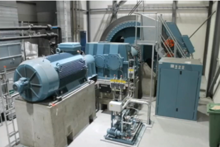
Figure 1: Mine Hoist
First, some basic working principles. The drum carries the load regardless of the rotation.
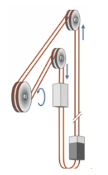
Figure 2: The drum is carrying the load
Figure 3 shows the gearbox. The drum rotates at 52 RPM. We were monitoring an issue on the gear’s output shaft at 52 RPM.

Figure 3: Gearbox
A unique feature of the skip hoist is that it travels in two different directions but always carries a load. Based on the rotation, the load changes from one side of the bearing to the other. Whether it is moving up or down, it will move from side to side.

Figure 4: Skip hoist
Figure 5 shows the two sets of data per signal—the lower line levels and the upper line levels, based on which direction the hoist was moving. In one direction, the load is on the good side of the bearing, so the amplitudes are not elevated. When the load is traveling in the other direction, the amplitude is higher.
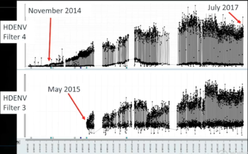
Figure 5: Each signal shows two sets of data
We started to see elevated signals in early November using Filter 4. Six months later, we started to see elevated signals in Filter 3. By July of 2017, the signal in Filter 4 started to decrease because the damage had matured.
There have been many instances where we have monitored a bearing for well over a year. The alarm is normally set on the low side in Filter 4 so that we can catch the point when the value begins to decrease. The decrease of the value gives us an indication that the fault is maturing.
In this case, we had almost three years of pre-warning time, as the value detected by Filter 4 began to increase in November of 2014 and decreased in July of 2017.
At 52 RPM, this is a low-speed machine but not an ultra-low-speed machine. Using our HD ENV technology, we produced a crisp and clean spectrum.
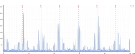
Figure 6: A crisp and clear spectrum
Figure 7 shows the gearbox and its output shaft.

Figure 7: The gearbox and output shaft
Upon inspection, the bearing was found to be damaged.
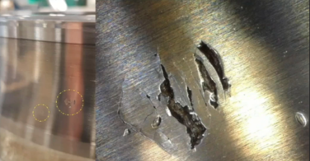
Figure 8: Damaged bearing
The bearing was replaced in July of 2017, and the signal fell to a minimal level.
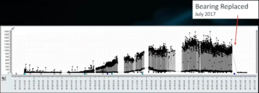
Figure 9: Signal after the bearing was replaced
